This project is a small part of a larger effort to recreate the Mycroft Mark1 with RISC-V.
The project is available to view on Codethink's GitLab.
Why RISC-V
Forgetting all the technical jibberish for a moment: RISC-V is just really cool. It's open hardware. That means that with the right skills and facilities, a person could take the specification, add to it and create their own custom hardware designs. They're able to do this for free, without having to pay a licensing fee.
RISC-V has the potential to disrupt the tech landscape in a big way. It's already finding its way into hard drive controllers and soldering irons. Beyond the embedded market (typically the domain of Arm CPUs and microcontrollers), it has eyes set on high performance compute where you'd typically find an x86 CPU (servers and desktops).
As a company, Codethink is interested in demonstrating that we can work with RISC-V microprocessors.
As an engineer, I feel like I've been given an opportunity to play with a new exciting technology.
The brief: Make a breakout board for a RISC-V microcontroller
The board should be a drop-in replacement for the Arduino ProMini. Thus it needs to have the same form factor as the ProMini, and pin compatibility with the ProMini. It would be nice if the board we produce could be made compatible with the Arduino ecosystem, such that our board could deploy a sketch made for the ProMini with minimal tweaking.
The only logical choice for the microcontroller: the GD32VF103CBT6 by GigaDevice
We used GD32VF103CBT6 by GigaDevice. This microprocessor was chosen because it is the only RISC-V microprocessor that we could feasibly get our hands on. Even then, finding a supply of the chosen chip was difficult. There are a couple of examples of dev boards with the GD32V that we did find (e.g., the longan nano). So the chips must be available somewhere. That said, after scouring the depths of AliExpress, talking to distributors and even approaching GigaDevice directly, we were unable to find a stand-alone supply of the chips. This was probably due to the global electronics shortage.
The GD32VF103CBT6 bears a striking similarity to STM's STM32F103CBT6 (a microprocessor with an Arm Cortex-M3 core). So in a worst-case scenario, we could just develop a board around the STM part while waiting for the availability of the GD32V to improve.
Ultimately, however, I ordered a bunch of Longan Nanos and removed the GD32Vs at our electronics workbench. This somehow works out cheaper than using the STM part. It was helpful that I just had some of these Longan boards knocking about my desk beforehand too. In the future, hopefully, LCSC will stock RISC-V microprocessors and help we could use them with JLCPCB's pick and place service.
Developing the board to match the Arduino ProMini's form-factor
I developed the board in KiCad, and unlike my first board, I was able to pester actual professionals to help put the design together. To date, this is the smallest and most densely packed board I've ever designed.
I tried to match the pins from the micro to their outputs in a way that matched what's on the ProMini, but there are some key differences:
- the ProMini comes in 3.3v and 5v varients. This board only operates at 3.3v, but all the inputs are 5v tolerant.
- the ATmega chips in Arduinos have distinct pins for digital and analogue functions. The GD part does not make that sort of distinction, and all pins can be used for both digital and analogue operations.
- the programmer header is different.
- the ProMini does not have a USB port. This board has a USB-micro port.
I didn't know what to do with the boot pin, so I added solder jumpers to the underside of the board to allow me to either bring it high, low or leave it floating.
After putting together a board that matches the Arduino ProMini's form-factor, we went to JLCPCB for a test run. I wanted to use JLCPCB's STM Assembly service, but it turns out the Arduino ProMini's form-factor is too thin to qualify for the Assembly service. Keeping everything else the same, I made the board wider and used the extra space for better pin labels (earlier designs had these on the bottom of the board). That's why the design seems to have wings. They are not electrically active and can be sanded off if need be.
The boards arrived after a short wait. They arrived without the microcontroller, since it isn't yet in JLCPCB's parts library. So I got to spend a few hours liberating the controllers from a 3rd party's devboard (Sipeed's Longan Nano) and attaching them to my own.
After doing that, I discovered two unfortunate things about this revision of the board; I failed to realise that SWDIO is exclusively an Arm cortex feature. It would not be possible to program the boards using the programmer header. And, when I defined the USB connector's footprint in kicad, I got the pin numbers in the wrong order. So I had wired the USB connector on backwards. So it would not be possible to program the boards using USB. And with these revelations, it dawned on me why those third party boards had jtag headers.
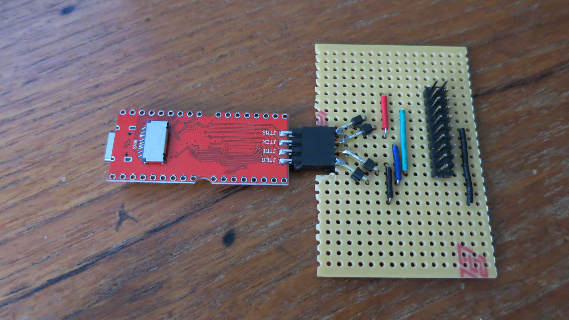
As luck would have it, the board I designed did happen to have all the necessary pins for jtag broken out. I got an ST-Link V3, which comes with an expansion board with a full sized, 20 pin jtag port. I also created this adapter board that would allow me to connect the disparate spattering of jtag pins to the jtag programmer.
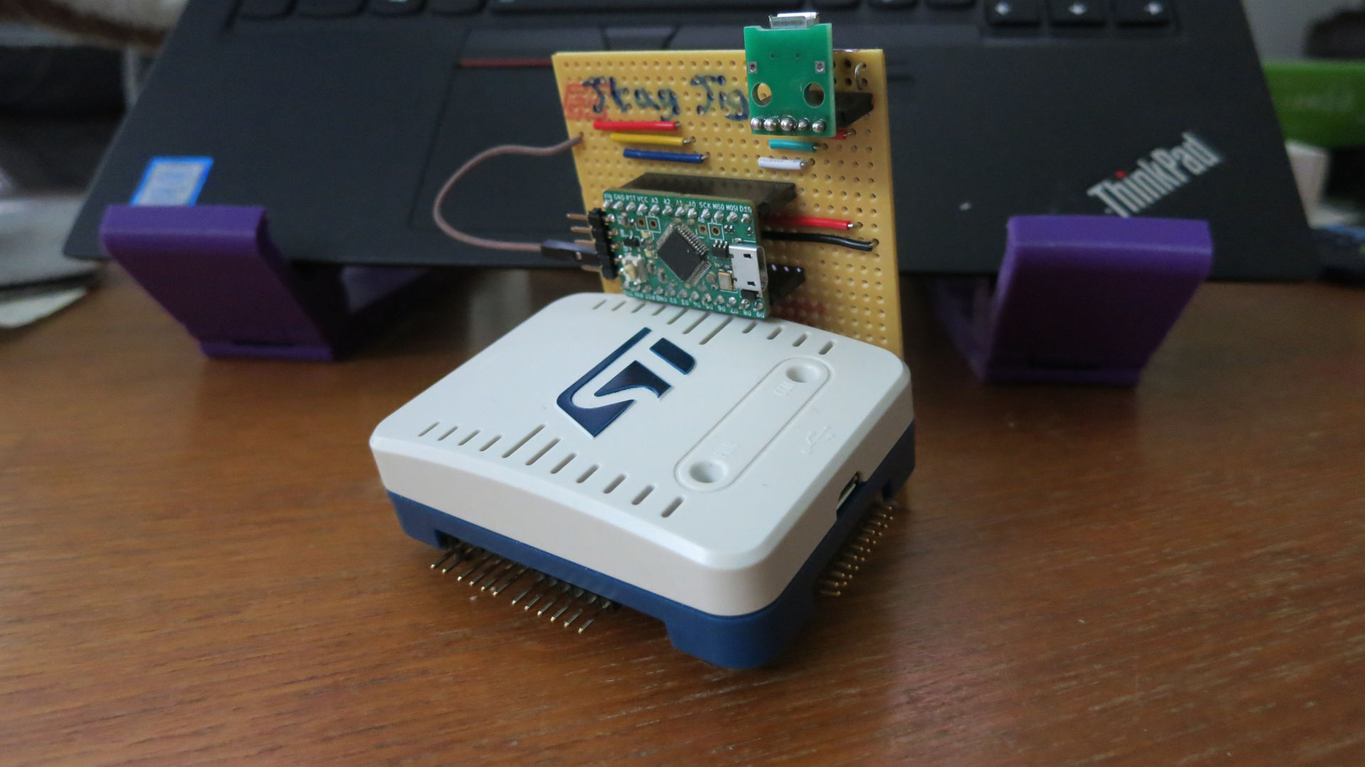
After doing all that, I found that I couldn't get the st-link to recognise the GD parts as viable targets. I'd have to find some other programmer. As luck would have it, I discovered the RV-Link project. This turns development boards with the RISC-V micros into jtag debuggers for programming other RISC-V dev boards that work by pairing up the jtag pins. I made this other board to Adapt the jtag header of the Longan Nano into a full-sized jtag port.
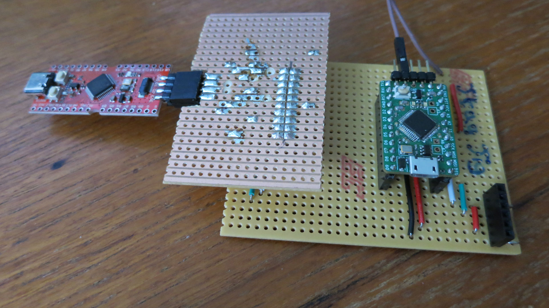
Thus using this Frankenstein's monster of a solution, it is now possible to program the dev board.
Software Enablement
The boards are programmable using platform.io. Since they share the same micro, you can treat these boards just like the Longan Nanos. Except these have to be programmed using the RV-link. Also, the boot jumper must be held high while being programmed but should be held low otherwise.
Fixing the faults
I fixed the above flaws in the next revision of the board.
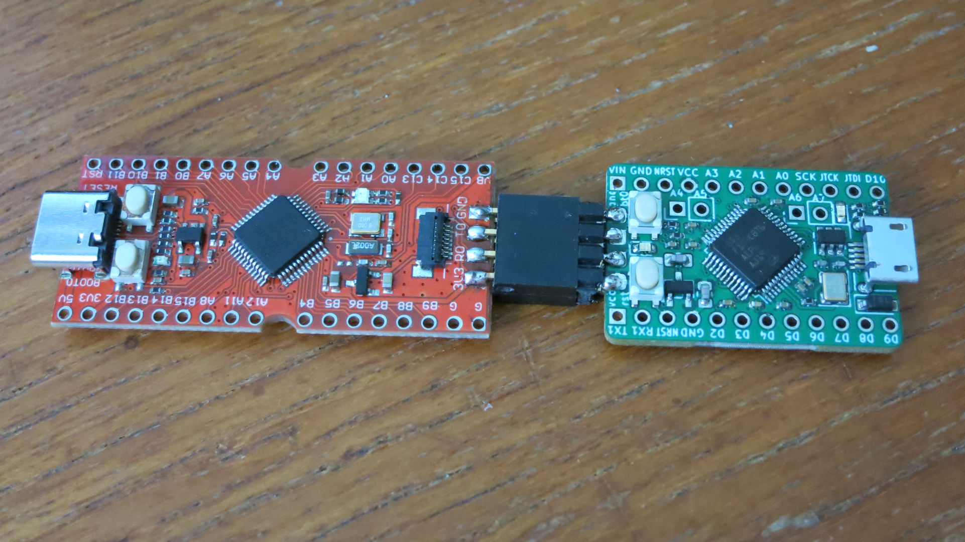
Version 2 has a functional USB port, a jtag header, and an extra button for the boot pin. I had to move the voltage regulator to be a little lower to accommodate a button, which replaces the boot pin's solder jumpers. The JTag header is a mirror of the RV-Link's JTag header, such that they can be connected directly together.
This is the most densely packed board I've designed.
The future
We hoped that this board could serve as a drop-in replacement for the Arduino-mini inside the Mycroft mark1. Because of the voltage issue mentioned at the beginning of this article, it isn't possible to use this board as a drop-in replacement. We'd need voltage level shifters for each of the pins, and there isn't room on this board.
Going forward, we can use this board and the experience gained from developing it in the future. The next steps will likely involve a custom faceplate for the mark1, which can either use this board or integrate with the microcontroller directly.
Keep up with our RISC-V news
Fill out the form to receive our latest updates on the open CPU architecture in your inbox.
Related blog posts:
- Previous research: RISC-V: Codethink's first research about the open instruction set >>
- Teams' thoughts about RISC-V: Meet the Codethings: Ben Dooks talks about Linux kernel and RISC-V >>
Other Content
- Codethink has achieved ISO 9001:2015 accreditation
- Outreachy internship: Improving end-to-end testing for GNOME
- Lessons learnt from building a distributed system in Rust
- FOSDEM 2024
- Introducing Web UI QAnvas and new features of Quality Assurance Daemon
- Outreachy: Supporting the open source community through mentorship programmes
- Using Git LFS and fast-import together
- Testing in a Box: Streamlining Embedded Systems Testing
- SDV Europe: What Codethink has planned
- How do Hardware Security Modules impact the automotive sector? The final blog in a three part discussion
- How do Hardware Security Modules impact the automotive sector? Part two of a three part discussion
- How do Hardware Security Modules impact the automotive sector? Part one of a three part discussion
- Automated Kernel Testing on RISC-V Hardware
- Automated end-to-end testing for Android Automotive on Hardware
- GUADEC 2023
- Embedded Open Source Summit 2023
- RISC-V: Exploring a Bug in Stack Unwinding
- Adding RISC-V Vector Cryptography Extension support to QEMU
- Introducing Our New Open-Source Tool: Quality Assurance Daemon
- Long Term Maintainability
- FOSDEM 2023
- Think before you Pip
- BuildStream 2.0 is here, just in time for the holidays!
- A Valuable & Comprehensive Firmware Code Review by Codethink
- GNOME OS & Atomic Upgrades on the PinePhone
- Flathub-Codethink Collaboration
- Codethink proudly sponsors GUADEC 2022
- Tracking Down an Obscure Reproducibility Bug in glibc
- Web app test automation with `cdt`
- FOSDEM Testing and Automation talk
- Protecting your project from dependency access problems
- Porting GNOME OS to Microchip's PolarFire Icicle Kit
- YAML Schemas: Validating Data without Writing Code
- Deterministic Construction Service
- Codethink becomes a Microchip Design Partner
- Hamsa: Using an NVIDIA Jetson Development Kit to create a fully open-source Robot Nano Hand
- Using STPA with software-intensive systems
- Codethink achieves ISO 26262 ASIL D Tool Certification
- RISC-V: running GNOME OS on SiFive hardware for the first time
- Automated Linux kernel testing
- Native compilation on Arm servers is so much faster now
- Higher quality of FOSS: How we are helping GNOME to improve their test pipeline
- Why aligning with open source mainline is the way to go
- Build Meetup 2021: The BuildTeam Community Event
- A new approach to software safety
- Does the "Hypocrite Commits" incident prove that Linux is unsafe?
- ABI Stability in freedesktop-sdk
- Why your organisation needs to embrace working in the open-source ecosystem
- Full archive